



Every time you key a repeater or tune a broadcast station, you are using one of radio’s most elegant ideas: hide the message in the frequency of the carrier, and leave the amplitude alone. That single design decision is why FM sounds clean, why a handheld can ride a hilltop repeater without hiss, and why the technique has outlived nearly a century of competition.
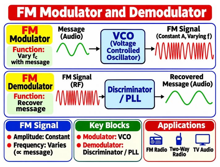
The starting point was a simple block diagram shared on Facebook (credit to its owner); the text, calculations and all illustrations here are original. Sources are listed at the end.
The diagram that started it
This one-page summary, shared on Facebook, captures the whole story at a glance: a VCO-based modulator on top, a discriminator or PLL demodulator below, and the key facts about FM along the bottom. The rest of this article unpacks each box.
1. The idea in one line
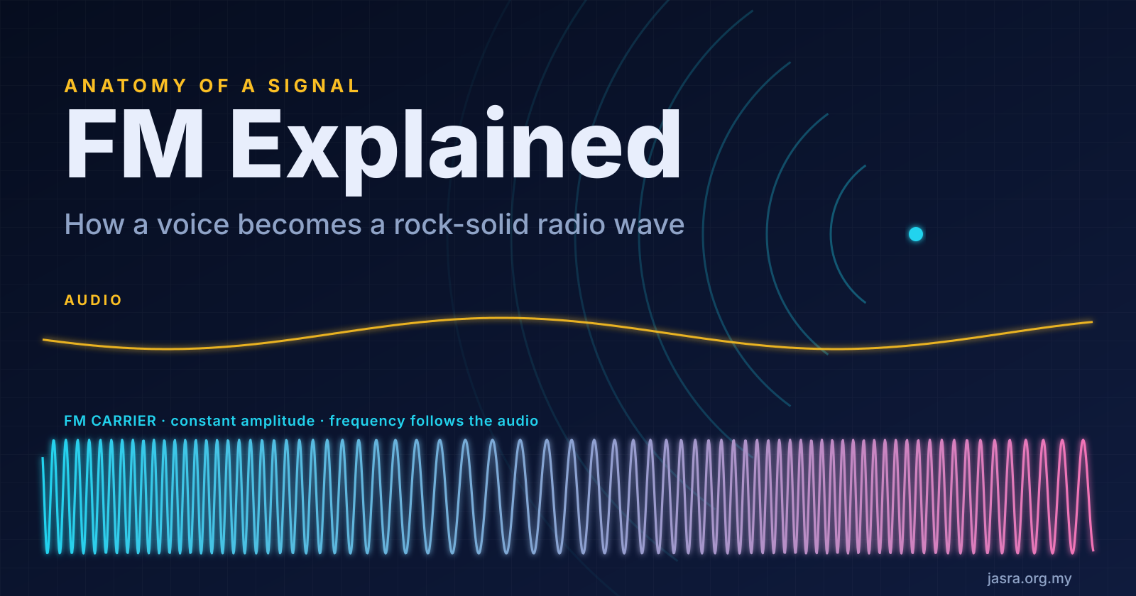
In frequency modulation the instantaneous frequency of the carrier moves away from its rest value fc in proportion to the message signal m(t):
f(t) = fc + kf · m(t)
The loudest point of the audio pushes the carrier up to its maximum deviation Δf; silence leaves it at fc. The ratio of deviation to the highest audio frequency is the modulation index, β = Δf / fm, the single number that decides how wide the signal is and how well it fights noise [1][4].
2. Why noise loses
Lightning, ignition systems and switching supplies add random amplitude spikes to the signal. An AM receiver cannot tell those spikes from the message. An FM receiver passes the signal through a limiter that flattens every amplitude variation, then reads only the frequency. The spikes are gone before detection even begins.
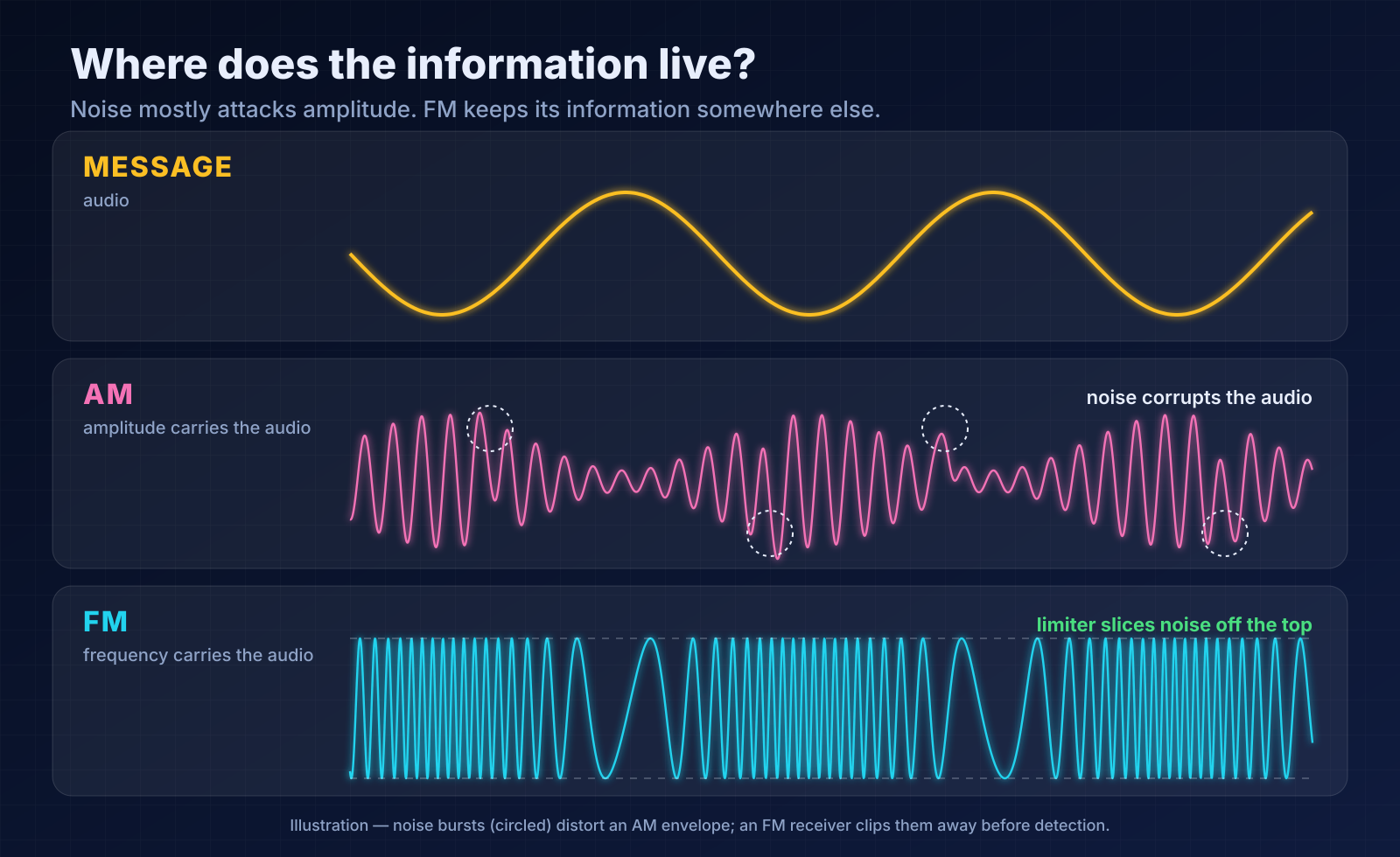
FM buys quiet audio with bandwidth. Past a minimum carrier-to-noise ratio the benefit collapses suddenly (the FM threshold), which is why a weak FM signal sounds worse than a weak SSB signal.
3. A short history: the idea nobody believed
In 1922 John R. Carson analysed frequency modulation and concluded that it gave no advantage over amplitude modulation for narrow deviation [2]. Edwin H. Armstrong disagreed: if the deviation is made large, noise rejection improves dramatically. He published the full case in the Proceedings of the IRE in May 1936 [1][5]. Wideband FM became the basis of high-fidelity broadcasting and, later, of two-way land-mobile and amateur VHF/UHF radio.
4. The transmitter: steering an oscillator
The modulator exists to vary fc with the message. In direct FM the audio, after pre-emphasis and a deviation limiter, drives a voltage-controlled oscillator (VCO), typically a varactor diode that changes the oscillator’s tuning capacitance. Frequency multipliers then raise both the carrier and the deviation to the operating frequency before the power amplifier. Indirect FM, Armstrong’s own method, instead phase-modulates a stable crystal oscillator and multiplies the result, trading a little complexity for excellent frequency stability.
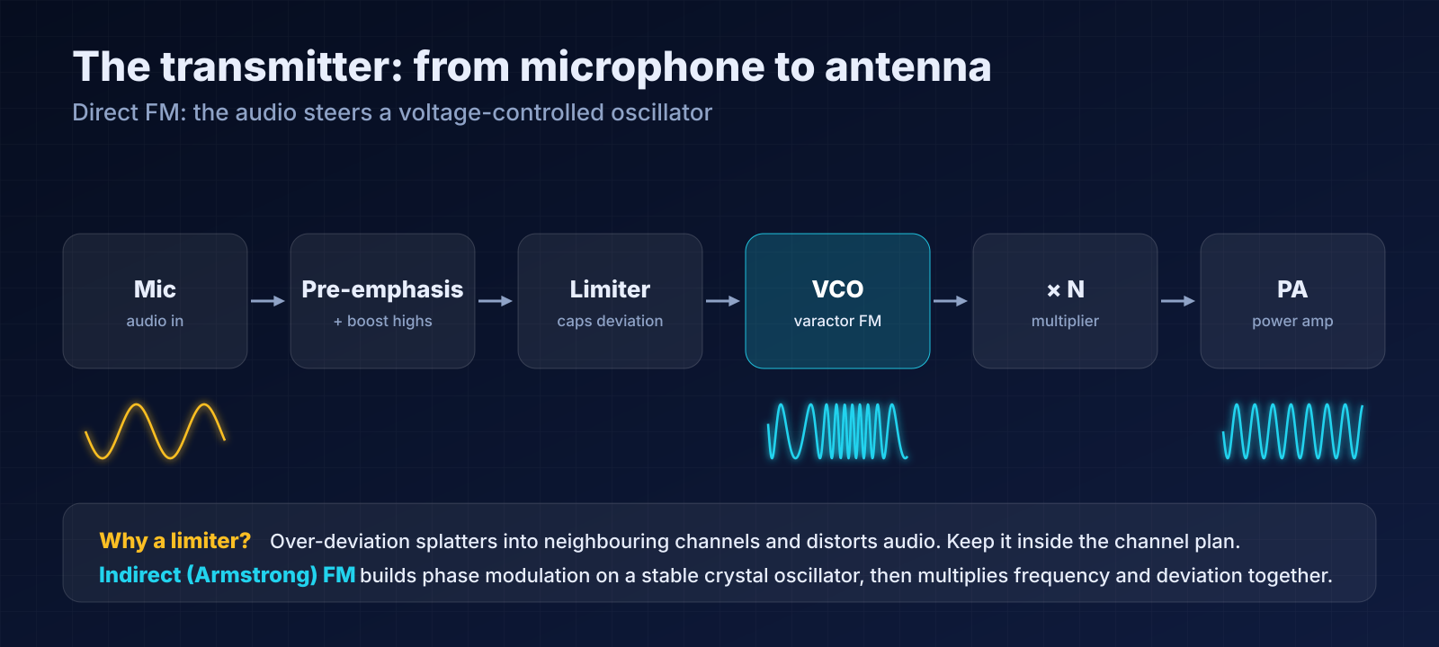
Pre-emphasis boosts high audio frequencies before transmission and the receiver’s de-emphasis undoes it, pushing hiss down without changing the audio. Broadcast standards specify a 50 µs or 75 µs time constant depending on region [3].
5. The spectrum: Bessel sidebands and Carson’s rule
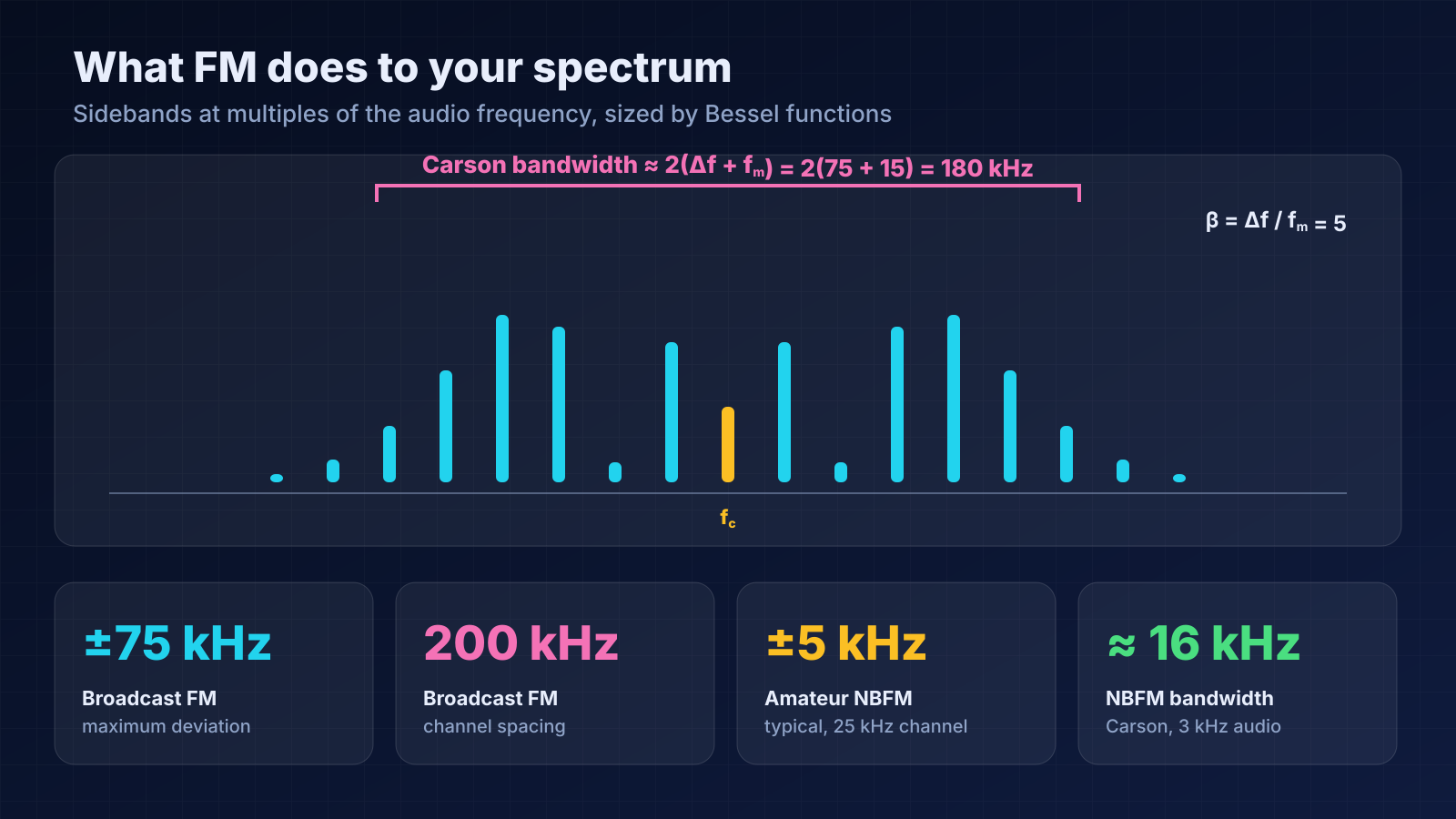
A single audio tone does not produce one sideband pair; it produces many, spaced by the tone frequency and sized by Bessel functions of the first kind, Jn(β). The practical shortcut is Carson’s rule [2][6]:
BW ≈ 2 (Δf + fm)
| System | Deviation | Top audio | β | Carson BW |
|---|---|---|---|---|
| Broadcast FM | ±75 kHz | 15 kHz | 5 | 180 kHz |
| Amateur NBFM, 25 kHz channels | ±5 kHz | 3 kHz | 1.7 | 16 kHz |
| Narrower NBFM, 12.5 kHz channels | ±2.5 kHz | 3 kHz | 0.8 | 11 kHz |
Values are typical; actual limits depend on the licence conditions and the equipment. Carson’s rule is an estimate that captures about 98% of the power.
6. The receiver: clip, detect, restore
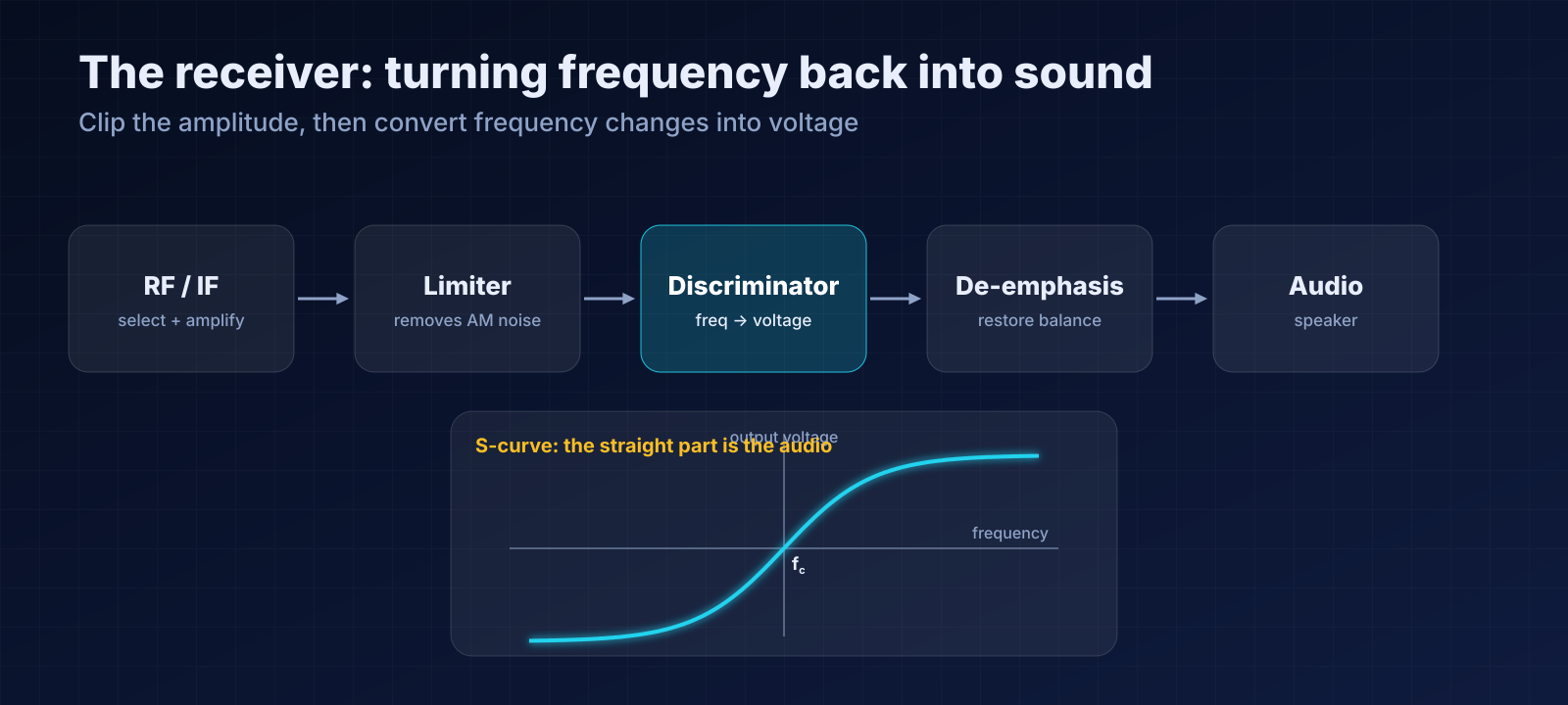
The receive chain mirrors the transmitter. After the RF and IF stages, the limiter strips amplitude noise, a discriminator or phase-locked loop converts frequency back into voltage, and de-emphasis restores the audio balance.
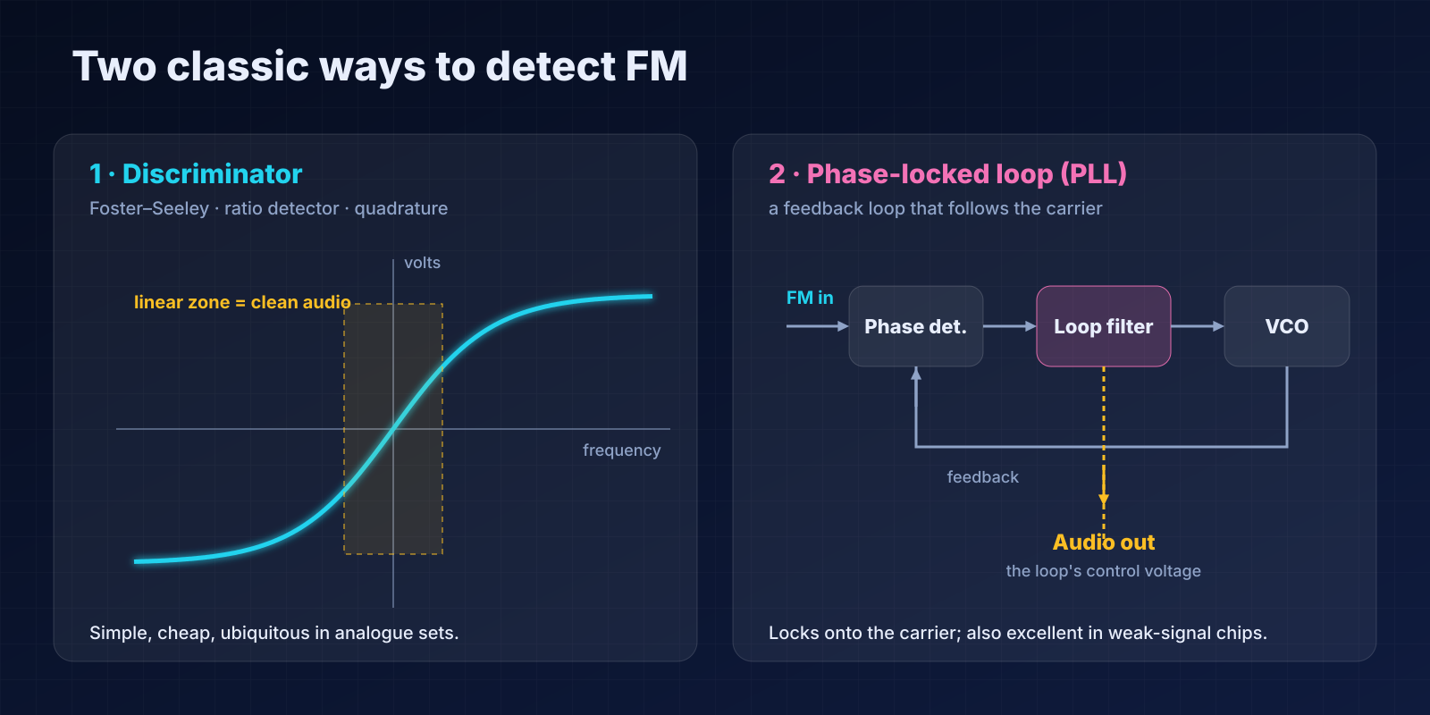
Two detector families dominate:
- Discriminators (Foster–Seeley, ratio detector, quadrature detector) use tuned circuits whose output voltage is proportional to how far the incoming frequency sits from the centre. Plot it and you get the famous S-curve; only the straight middle section gives clean audio.
- Phase-locked loops compare the incoming signal with a local VCO and steer it to follow. The voltage that keeps the VCO locked is the demodulated audio, and the loop keeps working at lower signal levels than a simple discriminator [7].
Modern receivers and software-defined radios often skip the analogue circuit altogether and compute the signal’s instantaneous frequency digitally from I/Q samples, but the principle is identical.
7. What this means on the air
- Mind your deviation. Speaking too close to a microphone with the gain high over-deviates the transmitter. Audio distorts and energy spills into adjacent channels.
- The capture effect is real. The stronger of two co-channel FM signals suppresses the weaker one almost completely, so doubling on a repeater is usually a loud-wins affair [8].
- Squelch is a hiss detector. With no carrier, a discriminator outputs loud noise; squelch listens to that noise above the voice band and mutes the speaker.
- Weak is worse than you expect. Below the FM threshold audio drops off a cliff. When a repeater is marginal, a little more antenna height or a better feedline often does more than extra power.
Tune an SDR to a local FM station and watch the spectrum: the carrier is never absent, but its sidebands breathe in and out as the music changes. That breathing is deviation, made visible.
Key takeaways
- FM keeps amplitude constant and puts the information in frequency.
- The modulator is a VCO (or phase modulator plus multiplier); the demodulator is a discriminator or PLL.
- Bandwidth follows Carson’s rule, BW ≈ 2(Δf + fm), so wider deviation means better noise performance and a wider channel.
- Good operating practice is simply good deviation control.
References
- E. H. Armstrong, “A Method of Reducing Disturbances in Radio Signaling by a System of Frequency Modulation,” Proceedings of the IRE, vol. 24, no. 5, pp. 689–740, May 1936. doi:10.1109/JRPROC.1936.227383
- J. R. Carson, “Notes on the Theory of Modulation,” Proceedings of the IRE, vol. 10, no. 1, pp. 57–64, Feb. 1922. doi:10.1109/JRPROC.1922.219793
- ITU-R Recommendation BS.450, Transmission standards for FM sound broadcasting at VHF. itu.int/rec/R-REC-BS.450
- “Frequency modulation,” Wikipedia. en.wikipedia.org/wiki/Frequency_modulation
- “Edwin Howard Armstrong,” Wikipedia. en.wikipedia.org/wiki/Edwin_Howard_Armstrong
- “Carson bandwidth rule,” Wikipedia. en.wikipedia.org/wiki/Carson_bandwidth_rule
- “Phase-locked loop,” Wikipedia. en.wikipedia.org/wiki/Phase-locked_loop
- “Capture effect,” Wikipedia. en.wikipedia.org/wiki/Capture_effect


