



Not every amateur radio operator has room for five separate antennas. A classic answer is the trapped long-wire antenna: a single end-fed wire with several LC traps that electrically “cut” the wire at each band. The Engineering Version 1.0 infographic below shows a complete 5-band design for 80m, 60m, 40m, 20m and 10m at 100 W PEP, from wire layout and trap values to tuning procedure and bill of materials (BOM).
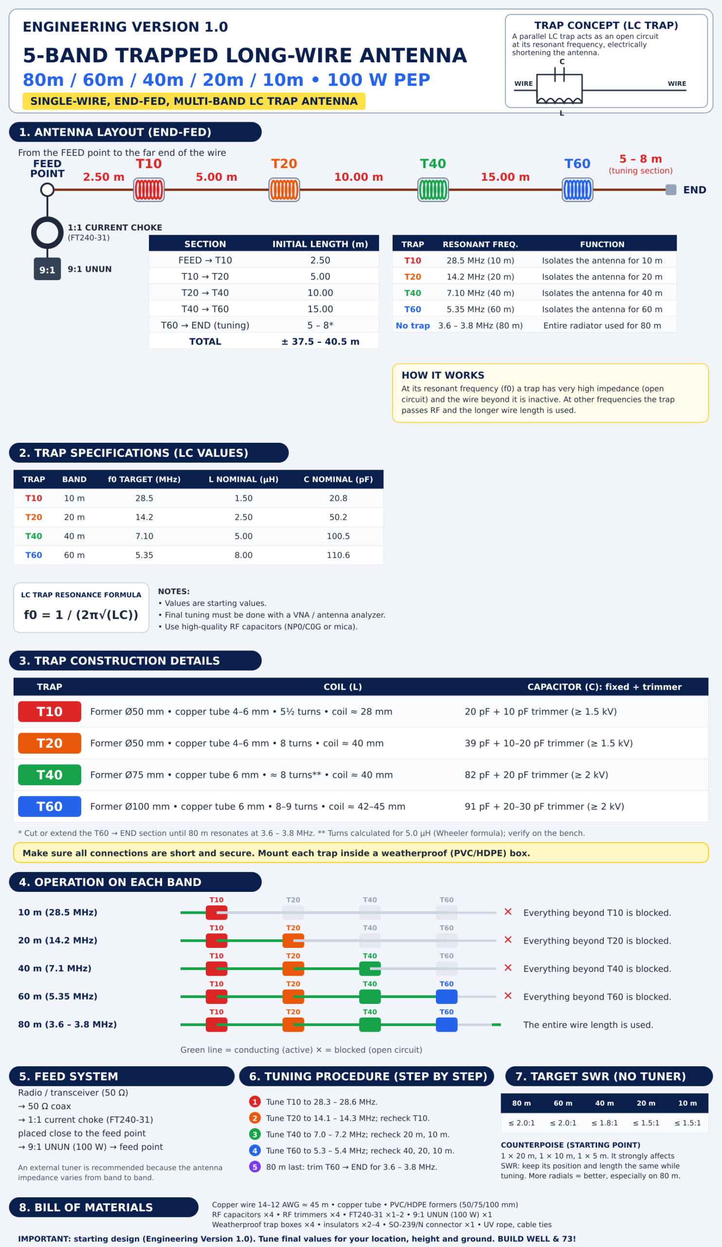
Infographic: 5-Band Trapped Long-Wire Antenna (click for full size).
The Concept: How an LC Trap Works
A trap is a parallel LC circuit placed in series with the wire. At its resonant frequency (f0 = 1 / 2π√LC), the trap’s impedance becomes very high, so it behaves like an open circuit and electrically shortens the antenna. At other frequencies the trap lets RF pass and the longer wire length is used.
By placing four traps at different distances, one wire becomes a resonant radiator for five bands. Trapped antennas have long been used in commercial and home-built designs; general background on wire antennas and tuning is available from the ARRL and Wikipedia.
Antenna Layout (End-Fed)
From the feed point to the far end, the wire and trap sequence is:
| Section | Initial length |
|---|---|
| Feed → T10 | 2.50 m |
| T10 → T20 | 5.00 m |
| T20 → T40 | 10.00 m |
| T40 → T60 | 15.00 m |
| T60 → end (tuning section) | 5 – 8 m |
| Total | ± 37.5 – 40.5 m |
What each trap does
| Trap | Resonant frequency | Function |
|---|---|---|
| T10 | 28.5 MHz | Isolates the antenna for the 10 m band |
| T20 | 14.2 MHz | Isolates the antenna for the 20 m band |
| T40 | 7.10 MHz | Isolates the antenna for the 40 m band |
| T60 | 5.35 MHz | Isolates the antenna for the 60 m band |
| No trap | 3.6 – 3.8 MHz | The entire radiator is used for 80 m |
In operation: on 10 m only the section from the feed to T10 is active; on 20 m, up to T20; on 40 m, up to T40; on 60 m, up to T60; and on 80 m the whole wire is used. Below a trap’s resonant frequency the trap behaves like a loading coil, so the physical length of each section does not equal its electrical length. This is why the starting values must be tuned with test equipment.
Trap Specification and Construction
| Trap | Target f0 | Nominal L | Nominal C | Coil (per the infographic) | Capacitor |
|---|---|---|---|---|---|
| T10 | 28.5 MHz | 1.50 µH | 20.8 pF | Ø50 mm former, 4–6 mm copper tube, 5½ turns, about 28 mm long | 20 pF + 10 pF trimmer (≥ 1.5 kV) |
| T20 | 14.2 MHz | 2.50 µH | 50.2 pF | Ø50 mm former, 4–6 mm copper tube, 8 turns, about 40 mm long | 39 pF + 10–20 pF trimmer (≥ 1.5 kV) |
| T40 | 7.10 MHz | 5.00 µH | 100.5 pF | Ø75 mm former, 6 mm copper tube, about 40 mm long | 82 pF + 20 pF trimmer (≥ 2 kV) |
| T60 | 5.35 MHz | 8.00 µH | 110.6 pF | Ø100 mm former, 6 mm copper tube, 8–9 turns, about 42–45 mm long | 91 pF + 20–30 pF trimmer (≥ 2 kV) |
Engineering check
I recalculated the values in the infographic, and they hold up well:
- L–C resonance: with f0 = 1 / 2π√LC, the L and C pairs in the table resonate at 28.49 MHz (T10), 14.21 MHz (T20), 7.10 MHz (T40) and 5.35 MHz (T60), matching the targets.
- Capacitors: the fixed-plus-trimmer combinations add up to the correct total for each trap.
- Coils: using Wheeler’s formula for a single-layer solenoid, T10 (Ø50 mm, 5½ turns, 28 mm) gives about 1.5 µH, T20 (8 turns, 40 mm) about 2.5 µH, and T60 (Ø100 mm, 8–9 turns, 43 mm) about 8 µH, all consistent with the nominal values.
- Caution on T40: the turn count for T40 is hard to read in the original picture. To get 5.0 µH on a Ø75 mm former about 40 mm long you need roughly 8 turns. If the original means 11 turns, the inductance would be around 9 µH and the trap would resonate too low. Recalculate before you build.
As the infographic states, all values are starting values. Final tuning must be done with a VNA or antenna analyzer, using high-quality RF capacitors (NP0/C0G or mica). Mount each trap in a weatherproof (PVC/HDPE) box and keep all connections short and secure.
Feed System
- Radio / transceiver (50 Ω)
- 50 Ω coax
- 1:1 current choke (FT240-31) close to the feed point, to stop common-mode current flowing on the outside of the coax; see baluns and chokes
- 9:1 UNUN (100 W) to transform the high impedance at the end of the wire down to roughly 50 Ω
- Feed point (end-fed)
The design notes recommend a 9:1 UNUN plus an external tuner, because the antenna impedance changes from band to band. See this overview of the antenna tuner.
Installation Examples
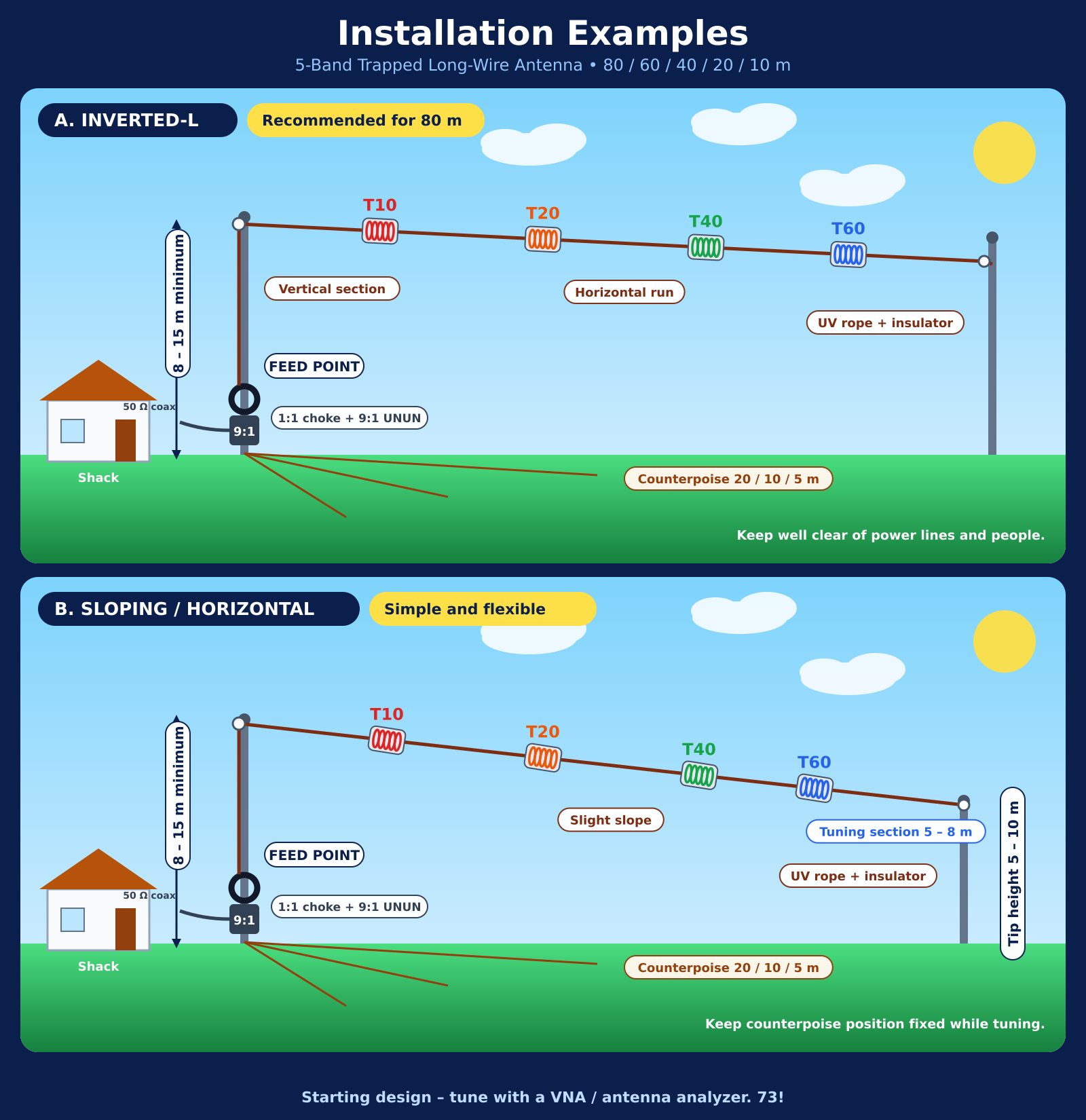
Illustration of both installation options (click for full size).
- A. Inverted-L (recommended for 80 m): a vertical section rises from the feed point, then the wire runs horizontally or slopes down. Minimum height 8–15 m. See Inverted-L antenna.
- B. Sloping / horizontal: a sloping or horizontal wire at 8–15 m minimum, with the far end at 5–10 m.
Use UV-resistant rope and insulators at the ends of the wire, and keep the antenna well away from power lines.
Counterpoise / Ground System
An end-fed antenna needs a return path for current. The infographic suggests a starting point of one 20 m, one 10 m and one 5 m counterpoise wire. The counterpoise strongly affects SWR and impedance, so keep its position and length the same while tuning. More radials generally give better performance, especially on 80 m. Reference: Counterpoise.
Tuning Procedure, Step by Step
- Tune T10: adjust the T10 capacitor for resonance at 28.3–28.6 MHz.
- Tune T20: adjust T20 for 14.1–14.3 MHz, then recheck T10.
- Tune T40: adjust T40 for 7.0–7.2 MHz, then recheck 20 m and 10 m.
- Tune T60: adjust T60 for 5.3–5.4 MHz, then recheck 40 m, 20 m and 10 m.
- Tune 80 m last: trim or extend the T60-to-end section until resonance falls at 3.6–3.8 MHz.
Use low power (a few watts) while tuning, and do not transmit outside the frequencies your licence allows.
Target SWR (Without a Tuner)
| Band | Target SWR |
|---|---|
| 80 m | ≤ 2.0:1 |
| 60 m | ≤ 2.0:1 |
| 40 m | ≤ 1.8:1 |
| 20 m | ≤ 1.5:1 |
| 10 m | ≤ 1.5:1 |
For more background, see standing wave ratio.
Bill of Materials (BOM)
| Item | Quantity |
|---|---|
| Copper wire (14–12 AWG), about 45 m | 1 set |
| Copper tube for the coils | 1 set |
| PVC/HDPE formers (50, 75, 100 mm) | 1 set |
| RF capacitors (20 pF, 50 pF, 100 pF, 110 pF), ≥ 1.5–2 kV | 4 pcs |
| RF trimmer capacitors (5–30 pF), ≥ 1.5–2 kV | 4 pcs |
| FT240-31 (1:1 choke) | 1–2 pcs |
| 9:1 UNUN (100 W) | 1 pc |
| Weatherproof trap boxes (PVC/HDPE) | 4 pcs |
| Insulators (roll / eye) | 2–4 pcs |
| SO-239 / N connector | 1 pc |
| UV rope and cable ties | As needed |
Professional Notes Before You Build
- High voltage at the traps: on an end-fed antenna, RF voltage on the wire and traps can be high. Use capacitors with adequate voltage ratings, keep good spacing and insulation, and never touch the antenna while transmitting.
- Loss and efficiency: each trap adds some loss, and coil and capacitor quality determine efficiency. Poor capacitors will heat up and drift in frequency.
- Tropical weather: heavy rain and humidity will detune traps if the boxes are not sealed. Use waterproof boxes, drip loops and sealed connectors.
- The 60 m band: the 5.3 MHz allocation is not the same in every country. Confirm its status and conditions in Malaysia with MCMC before transmitting.
- Safety: keep the antenna away from power lines and public areas, install it safely, and never work at height during a thunderstorm.
- Version 1.0 is a starting point: as the infographic itself says, final values must be tuned for your location, height, ground and surroundings.
Conclusion
The trapped long-wire antenna shows how one well-designed wire can serve many bands at low cost. With correct resonance calculations, quality components, a 1:1 choke, a good counterpoise and careful tuning with a VNA, it is a practical option for stations with limited space. Build it, test it, and share your results with the JASRA community.
Happy building & 73!
References: ARRL – Antennas · Wikipedia – LC circuit · Wikipedia – Inductance · Wikipedia – Random wire antenna · Wikipedia – Inverted-L antenna · Wikipedia – Counterpoise · Wikipedia – Balun · Wikipedia – Antenna tuner · Wikipedia – SWR · Wikipedia – VNA · MCMC · IARU
This article is also available in Malay: Antena Wayar Tunggal Berperangkap 5-Band.


