



Eleven metres of boom, three elements of up to 22.8 m, and a signal that can jump across the world on 7 MHz. This is the story of how a drawing on Facebook became a lesson in building the biggest antenna most radio amateurs will ever dream about, with the numbers worked out so you can see what it would really do.
A story from the club field
(An illustrative story. The characters are fictional, and all numbers in this article come from the drawing or from calculations explained below.)
Amir, who now has his 2 m Yagi working well, comes to the club station on a Saturday with his phone in his hand. “Pak Long, look at this drawing someone shared. A three-element beam for 40 metres. Eleven metres of boom! Why would anyone build that?”
Pak Long, the club’s senior member, smiles and goes to the whiteboard. “Because 40 m is the band that never sleeps. In the day it gives you Asia and Australia, and at night it opens to Europe and beyond. But on 40 m even a small mistake costs you metres, not millimetres. Let us read your drawing together, number by number, and I will show you what it would do.”
An hour later the whiteboard is full, Amir has a page of notes, and he has learned something he did not expect: the drawing has everything you need to build the antenna except the part that says whether it works. So they checked that too. This article is the whiteboard.
Why a 40 m beam is a giant
Radio waves on 7.05 MHz are 42.5 metres long (wavelength = 299.8 ÷ frequency in MHz). A half-wave dipole is therefore about 20 to 21 m, and a Yagi built from three such elements needs a boom of about a quarter wavelength or more, here 11 m, or 0.26 λ. Compare that with a 2 m band Yagi, where the whole antenna fits in a car.
A Yagi–Uda antenna is a dipole (the driven element) with a slightly longer reflector behind it and a slightly shorter director in front of it. The extra elements are not connected to the radio; they re-radiate the signal with the right timing so that it adds up in front and cancels behind.
That design was announced by Hidetsugu Yagi in 1928 (reference 1), based on the work of his colleague Shintaro Uda. A century later it is still the king of HF beams, because it does something no wire antenna can do: it puts all the power in one direction, and it shrinks the noise and interference from the other side.
Reading the drawing
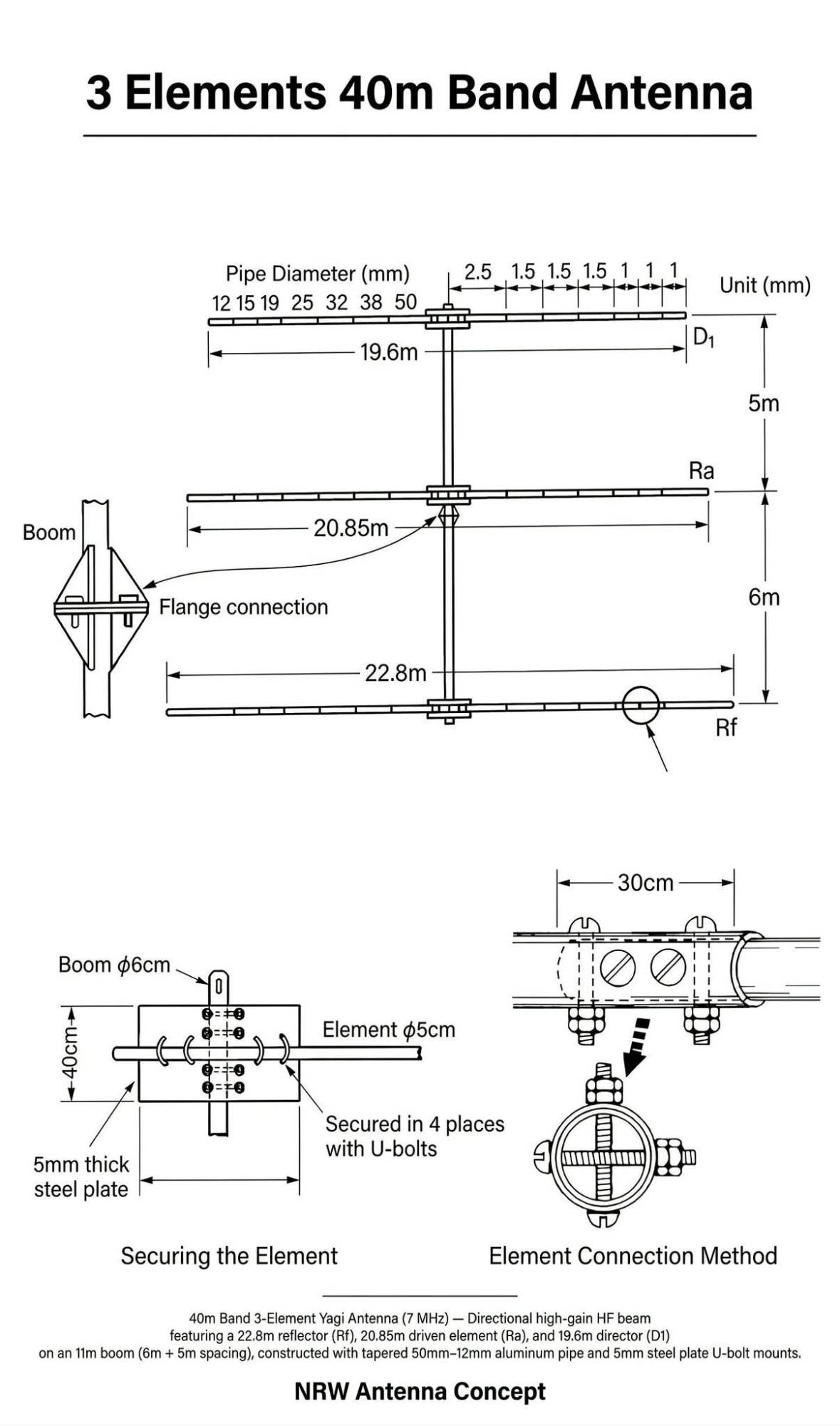
The drawing gives the three element lengths, two spacings and the boom. Putting them next to each other shows the logic of the design:
| Element | Length | In wavelengths (7.05 MHz) | Compared with driven | Spacing from the next element |
|---|---|---|---|---|
| Reflector Rf | 22.8 m | 0.536 λ | 109 % | 6 m (0.141 λ) to Ra |
| Driven element Ra | 20.85 m | 0.490 λ | 100 % | 5 m (0.118 λ) to D1 |
| Director D1 | 19.6 m | 0.461 λ | 94 % | – |
Ratios are rounded. The classic “rule of thumb” for a three-element Yagi is a reflector about 5 % longer and a director about 5 % shorter than the driven element (reference 2); this drawing uses about 9 % and 6 %, so it is a little more generous at the back.
Three things stand out:
- The spacings are tight. 0.12 to 0.14 λ is close. The boom stays at a manageable 11 m, but the element-to-element coupling is strong, which pulls the driven element’s impedance well below 50 Ω (we will calculate how far).
- The elements are not straight pipes. Each one tapers from Ø50 mm at the boom to Ø12 mm at the tip, which saves weight and wind load where it matters most.
- The “mm” label is a typo. The sections 2.5, 1.5, 1.5, 1.5, 1, 1 and 1 add up to exactly 10 m, which is half of a 20 m element. The drawing prints the unit as “mm”, but they can only be metres.
The taper trick: seven pipes in one element
Nobody sells a 23 m aluminium pipe. The solution is the oldest trick in amateur antenna building: telescoping tubing. Each size slides into the next with about 30 cm of overlap, and is locked with a stainless clamp or screws (the right-hand detail in the drawing). The overlapped section is stiffer, which helps, because the pipe is stressed most near the boom.
The seven sections add up to a 20 m element (10 m per side). That is almost exactly the director (19.6 m, 9.8 m per side). The driven element and reflector need extra tip length, which is added by letting the Ø12 mm tip stick out further: +0.43 m per side on Ra and +1.40 m on Rf. A long, thin tip is the weakest part, so a short fibreglass or aluminium tip support, or a guy line to the boom truss, is worth considering for the reflector.
What would it actually do? The calculation
A drawing does not tell you how well an antenna works, so we modelled the exact dimensions above. The method is explained at the end of this section so that you can judge how far to trust the numbers.
Impedance and VSWR. At 7.05 MHz the driven element presents about 34 Ω to the feed line, with no reactance, so the match to 50 Ω coax is a VSWR of about 1.5:1. That is typical of a closely spaced three-element Yagi. The impedance is a bit below 50 Ω at the bottom of the band, and the antenna “resonates” near 7.05 MHz.
Gain and front-to-back. The gain rises across the band (about 6.9 dBi at 7.0 MHz to 7.7 dBi at 7.2 MHz), but the front-to-back ratio gets worse as you go up. The sweet spot, where the reflector and director are working best together, is at the low end: about 25 dB of front-to-back at 7.0 to 7.05 MHz.
| Frequency (MHz) | Feed-point impedance | VSWR on 50 Ω | Gain (free space) | Front-to-back |
|---|---|---|---|---|
| 6.95 | 41 − j12 Ω | 1.39 : 1 | 6.8 dBi | 23 dB |
| 7.00 | 38 − j7 Ω | 1.37 : 1 | 6.9 dBi | 25 dB |
| 7.05 | 34 − j0 Ω | 1.48 : 1 | 7.1 dBi | 25 dB |
| 7.10 | 29 + j7 Ω | 1.78 : 1 | 7.3 dBi | 21 dB |
| 7.15 | 24 + j16 Ω | 2.35 : 1 | 7.5 dBi | 17 dB |
| 7.20 | 19 + j27 Ω | 3.41 : 1 | 7.7 dBi | 13 dB |
Free-space values calculated for the dimensions in the drawing. A real antenna over ground will show changes in impedance and gain (see the section on height).
About 7 dBi is roughly 4.9 dB better than a simple dipole (2.15 dBi). One S-unit is about 6 dB, so the receiving station sees your signal almost one S-unit stronger. 25 dB of front-to-back means that signals and noise arriving from behind the antenna are reduced by around four S-units, which helps a lot on a crowded 40 m band. VSWR below 2:1 from 6.9 to about 7.12 MHz covers the CW and digital segments and the start of the SSB section without a tuner.
The beam is about 67° wide at the half-power points when you look from above, so the antenna does not need to be pointed precisely: a rotator that is a few degrees off will not matter. It is a fairly broad, friendly beam, which is what you want on a band where propagation paths wander.
If you want to operate higher in the band. The VSWR reaches 2:1 near 7.125 MHz and 3.4:1 at 7.2 MHz. Frequency is inversely proportional to length, so making all three elements about 1 % shorter moves the whole curve up by roughly 70 kHz. That is the cheap way to re-centre the antenna on the part of the band you use most. The best front-to-back stays near the centre of the curve, so tune the design for the part of the band that matters to you.
The calculation uses the classic induced-EMF method with sinusoidal current on each element (references 5 and 6), written for this article and checked against the textbook half-wave dipole (73 + j42 Ω and 2.15 dBi, which it reproduced). Each tapered element is replaced by a single straight pipe of the same average diameter, about 31 mm. It ignores the ground, the boom, the plates and the end effects of the tips. A professional design would be checked with a NEC program (references 8 and 9) before any pipe is cut. Treat the figures as a good guide, typically within a few percent in frequency and a fraction of a dB in gain, not as a guarantee.
Feeding it: a 1:1 balun or an “ugly balun”
The antenna is a balanced device: the two halves of the driven element carry equal and opposite currents. Coaxial cable is unbalanced. If you connect one to the other directly, part of the current spills onto the outside of the coax and the cable becomes part of the antenna. The pattern is distorted, noise from the shack travels up the cable, and the VSWR reading changes when you touch the cable. A balun (balanced-to-unbalanced) cures this.
Two good choices for a 40 m Yagi:
- A 1:1 current balun in a weatherproof box, wound on ferrite cores, rated for your power. It does not change the impedance: it only separates balanced from unbalanced. With 34 Ω at the feed point, the coax sees a VSWR of 1.5:1, which is fine and needs no further matching network.
- An “ugly balun”, the popular name for a quick choke made by slipping a string of ferrite beads over the coax at the feed point (or by coiling the coax itself into several turns). It looks messy, but it works: the common-mode current on the outside of the braid meets a high impedance, while the signal inside the cable is not affected. The target is a choking impedance of several thousand ohms at 7 MHz. Use beads of a type designed for HF (type 31 or 43 are common), check the manufacturer’s data, and expect to use dozens of beads. Always rate the choke for the power you intend to run (see reference 7).
The steel plate in the drawing is fine for the reflector and the director, which can be bonded to the boom: their centre point carries almost no voltage. The driven element is different. Its two halves must be insulated from the boom and from each other, which is why the feed picture shows a plastic or fibreglass plate. A small gap and two stainless screws are the feed point.
If the measured VSWR is higher than you want at your favourite frequency, a few more options exist (a hairpin or beta match, a gamma match, or a quarter-wave transformer). Your own tests with an antenna analyser will tell you which, if any, is worth the work; see the references (3 and 2) for design details.
Height above ground: where the signal goes
A horizontal antenna’s take-off angle depends on its height above ground, not on the antenna itself. Roughly speaking, the lowest strong lobe leaves at an angle of arcsin(λ ÷ 4h), with h the height. For 40 m (λ ≈ 42.5 m):
| Height above ground | In wavelengths | Lowest strong lobe leaves the antenna at about | Good for |
|---|---|---|---|
| 15 m | 0.35 λ | 45° | Local and regional contacts, high angle (NVIS-like) |
| 21 m | 0.49 λ | 30° | General all-round use |
| 30 m | 0.71 λ | 21° | Mixed local and DX |
| 42 m | 0.99 λ | 15° | DX: low, long-distance angle |
For long-distance (DX) work the angle should be low, so every metre of height helps. At 15 m the antenna is still very useful for contacts within a few thousand kilometres, because the high angle is better for them. Ground also changes the feed-point impedance by a few ohms as the height changes, so re-measure the VSWR on the tower and not on the ground. See the earlier JASRA article “Antenna Height vs Communication Range” (reference 16) for the full story.
The mechanical side: this is a structure, not a wire
The drawing’s mounting details show what a serious build needs:
- Plate and U-bolts. Each element sits on a 5 mm steel plate, 40 cm wide, on the Ø60 mm boom, and is held by four U-bolts (two on the element, two on the boom). The plate spreads the load, which is important because a 10 m cantilever is a very long lever.
- Telescoping joints. A 30 cm overlap, slotted and clamped with stainless hardware, plus antioxidant paste.
- Dissimilar metals. Steel, aluminium and stainless steel in contact in a wet climate can corrode quickly (reference 15). Hot-dip galvanise the plates, use stainless fasteners, and coat each joint with antioxidant paste.
- Boom truss. An 11 m boom with about 75 kg on it will sag. A stainless truss cable from a short mast above the boom takes the load and keeps the elements level.
| Part | Assumption | Approx. mass |
|---|---|---|
| 3 tapered elements (about 63 m of pipe in total) | aluminium, 2 mm wall (3 mm wall: about 43 kg) | ≈ 30 kg |
| Boom, 11 m | aluminium, Ø60 mm × 3 mm | ≈ 16 kg |
| 3 mounting plates | steel, 5 mm × 40 cm × 40 cm each | ≈ 19 kg |
| U-bolts, clamps, insulator plate, boom truss, cable | estimate | ≈ 10 kg |
| Total, ready to lift | ≈ 75 kg (up to about 95 kg with heavier pipe) |
Two more numbers matter when you plan the tower and the rotator. The projected area of the pipes and the boom is about 2.6 m²; in a 100 km/h gust this gives a force of roughly 1.5 kN (about 150 kgf). And the turning radius, from the boom centre to a reflector tip, is about 12.7 m: you need a clear circle of 25 m across for the antenna to rotate through, away from guy wires, trees and neighbours’ roofs.
Realistically, a three-element 40 m Yagi is a project for a club, a contest group or a very dedicated individual, with a proper tower (or a crank-up) and a heavy-duty rotator. If that is not possible, a two-element version or a rotatable dipole gives most of the benefit with a fraction of the weight.
Raising a big antenna is dangerous, and contact with power lines has killed radio amateurs. Never raise or lower the antenna near power lines: keep a clear distance of at least 1.5 times the total height of the structure. Work with at least two helpers, use proper climbing gear, wear a helmet, avoid lifting in wind, and ask a qualified rigger or the club’s experienced members to check the plan. Check local rules and permissions for the tower and the antenna before you build.
Build and tune: a tick list
- ☐ Check the unit mistake: the taper sections are in metres.
- ☐ Cut and mark the seven pipe sections; add tip lengths for Ra (+0.43 m per side) and Rf (+1.40 m per side).
- ☐ Check the nested sizes: only a little play, with antioxidant paste on every joint.
- ☐ Drill and fit the plates and U-bolts; insulate the driven element.
- ☐ Assemble the elements on the boom on the ground, check the spacings (6 m and 5 m) with a tape.
- ☐ Fit the 1:1 balun or the ferrite-bead choke, and seal the connectors.
- ☐ Lift to the working height (see the safety box).
- ☐ Measure the VSWR across 6.9–7.3 MHz with an antenna analyser. Find the lowest point, and tune by changing the tip length of the driven element.
- ☐ Check the front-to-back with a friendly local station: turn the beam and note the signal drop.
- ☐ Write the results in a log, including photos, date and weather.
What Amir did next
Amir did not build the 40 m Yagi that year. Instead he put the numbers in a spreadsheet and drew the tower on paper with Pak Long: 21 m high, 12.7 m turning radius, and a heavy-duty rotator at the top. “It is a dream with a date,” Pak Long said. “Now you know what the dream weighs.” The following month the club agreed to start with a 2-element version on a crank-up mast, to learn the mechanics before going full size.
Key takeaways
- A 40 m Yagi is big because 40 m is long: λ is about 42 m, so elements of 20 to 23 m and a boom of 11 m are normal.
- The drawing’s “mm” on the taper schedule is a typo: they are metres (10 m per half-element).
- Calculated for the dimensions shown: about 7 dBi (4.9 dB over a dipole), 25 dB front-to-back near 7.0–7.05 MHz, a feed-point impedance of about 34 Ω and VSWR below 2:1 from 6.9 to about 7.12 MHz.
- A 1:1 current balun or an “ugly balun” choke is enough for the feed; it does not change the impedance, it stops current on the outside of the coax.
- The driven element must be insulated from the boom; the others can be bonded.
- Plan for about 75–95 kg, a 12.7 m turning radius and a real tower. Check with NEC software before cutting metal, and put safety first.
References and further reading
- Yagi, H. “Beam transmission of ultra short waves.” Proceedings of the IRE, vol. 16, no. 6, June 1928, pp. 715–740. The paper that introduced the antenna to the English-speaking world.
- Viezbicke, P. P. Yagi Antenna Design. U.S. National Bureau of Standards, Technical Note 688, December 1976. Measured element lengths, spacings and gains for many Yagi designs. https://nvlpubs.nist.gov/nistpubs/Legacy/TN/nbstechnicalnote688.pdf
- ARRL. The ARRL Antenna Book (current edition). Yagi design, feed methods, baluns, towers and rotators. https://www.arrl.org/arrl-antenna-book
- Balanis, C. A. Antenna Theory: Analysis and Design, 4th ed., Wiley, 2016. Dipole, array and Yagi theory.
- King, R. W. P. The Theory of Linear Antennas. Harvard University Press, 1956. Source of the closed-form self and mutual impedance integrals used for the calculations in this article.
- Carter, P. S. “Circuit relations in radiating systems and applications to antenna problems.” Proceedings of the IRE, vol. 20, no. 6, 1932, pp. 1004–1041. The induced-EMF method for coupled elements.
- Sevick, J. Understanding, Building, and Using Baluns and Ununs. CQ Communications, 2003. Current baluns, chokes and ferrite beads for amateur use.
- Burke, G. J. and Poggio, A. J. Numerical Electromagnetics Code (NEC) – Method of Moments. Lawrence Livermore Laboratory, 1981. The standard method for checking a design before building it.
- 4nec2, free NEC-based antenna modelling software by Arie Voors. https://www.qsl.net/4nec2/
- Wikipedia: Yagi–Uda antenna https://en.wikipedia.org/wiki/Yagi%E2%80%93Uda_antenna
- Wikipedia: 40-meter band https://en.wikipedia.org/wiki/40-meter_band
- Wikipedia: Balun https://en.wikipedia.org/wiki/Balun
- Wikipedia: Standing wave ratio https://en.wikipedia.org/wiki/Standing_wave_ratio
- Wikipedia: Numerical Electromagnetics Code https://en.wikipedia.org/wiki/Numerical_Electromagnetics_Code
- Wikipedia: Galvanic corrosion (why steel, aluminium and stainless need care when joined) https://en.wikipedia.org/wiki/Galvanic_corrosion
- JASRA: Antenna Height vs Communication Range https://www.jasra.org.my/antenna-height-vs-communication-range/
- JASRA: Antenna Parameters Explained https://www.jasra.org.my/antenna-parameters-explained/
- Drawing “3 Elements 40m Band Antenna”, NRW Antenna Concept, shared in a Facebook post (shared for education; original creator’s details not given beyond that name). https://web.facebook.com/photo/?fbid=1174013725583585&set=a.373728765612089
The performance figures, tables and charts in this article were calculated for the dimensions in the drawing with the method described above; the illustrations are original JASRA drawings, and the layout drawing is to scale. The story and its characters are fictional. The drawing at the top is shared for educational purposes; the original creator is not named beyond “NRW Antenna Concept”. This article is a learning guide, not a construction specification: always verify a design with proper modelling and follow safety rules when building and raising antennas.


