



Disclosure: this article was written with the help of an AI assistant for JASRA members and students of amateur radio. The circuits are educational concept diagrams. They have not been built or measured by JASRA, so read the accuracy note below before you pick up a soldering iron.
A Saturday at the Club Workbench
A newly licensed operator arrives at the club room with two circuit pictures on a phone. One is a 2 m (145 MHz) FM transmitter and the other is a 70 cm (433 MHz) version. “It only has two or three transistors,” they say, “so why does it look so complicated?”
The club Elmer smiles, takes a pencil and says: “Every stage in this circuit has one small job. Learn the jobs and the circuit becomes a story you can read.”
This article follows that conversation. Along the way we cover crystals, resonance, harmonics, frequency modulation, filtering and antennas, the same ideas behind almost every radio you will ever use.
First, an Honest Accuracy Note
The author of the pictures was not sure they were correct, so we checked the numbers, and the lesson is worth keeping:
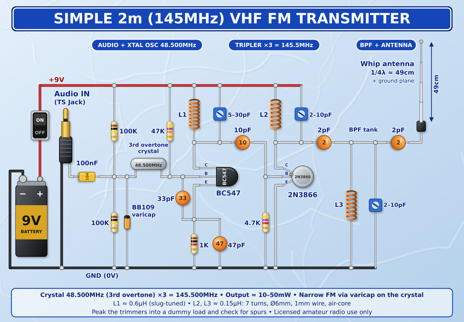
- The 2 m circuit is consistent. 48.500 MHz × 3 = 145.500 MHz. The ¼-wave whip of about 49 cm is correct, and the coil and capacitor values resonate where they should (shown below).
- The 70 cm circuit had a labelling error. A 48.200 MHz crystal gives 48.200 × 3 = 144.6 MHz after the first tripler, not 145.5 MHz. After the second tripler it is 144.6 × 3 = 433.8 MHz, which matches the footer. We corrected the label in the picture below. A small slip like this on a bench would leave you hunting for a signal on the wrong frequency.
- Output power claims are optimistic. “10–50 mW” and “5–20 mW” are best-case figures. Expect a few milliwatts to a few tens of milliwatts, and less on 70 cm where every multiplier stage loses efficiency.
- Missing practical details. The diagrams show no supply decoupling, no audio level control or limiter, and no screening. Real VHF/UHF builds need all three (see “Before you build”).
The Big Picture: Four Jobs, Four Stages
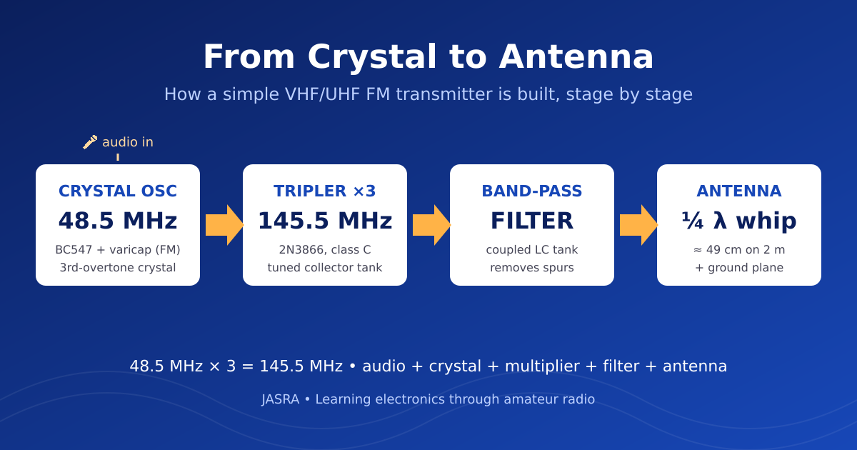
- Make a stable signal. A crystal oscillator at 48.5 MHz.
- Put the voice on it. A varicap diode nudges the frequency in step with the audio (FM).
- Multiply it up. A class-C stage with a tuned tank turns 48.5 MHz into 145.5 MHz.
- Clean it and radiate it. A band-pass filter and a ¼-wave whip antenna.
Stage 1: The Crystal Oscillator (BC547)
A quartz crystal is a mechanical resonator that vibrates at a very precise frequency, which is why it keeps a transmitter on channel. Crystals for these frequencies are usually overtone crystals. A crystal marked 48.500 MHz is really a ~16.17 MHz plate (48.5 ÷ 3) forced to vibrate on its 3rd overtone. If the circuit is not designed carefully it will happily oscillate at 16.17 MHz instead.
That is why the BC547 collector has a tuned circuit, L1 with the 5–30 pF trimmer. It must be tuned to the overtone frequency, not the fundamental. Using the resonance formula:
f = 1 / (2π√(LC))
With L1 ≈ 0.6 µH, the capacitance needed for 48.5 MHz is about 18 pF, comfortably inside the range of the trimmer plus the circuit’s stray capacitance. Slug-tuning L1 and adjusting the trimmer are the first tuning steps.
Making it FM with a varicap
A varicap (a diode used as a voltage-controlled capacitor, here a BB109) sits in series with the crystal. The two 100 kΩ resistors give it a steady reverse bias of about half the supply, and the 100 nF capacitor lets the audio ride on top. When the audio swings, the diode capacitance changes slightly, which “pulls” the crystal by a tiny amount. A crystal cannot be pulled far, which is a blessing, because only a small deviation is needed (see Stage 2).
Stage 2: Multiplying the Frequency (2N3866)
The 2N3866 is a VHF/UHF transistor with a base resistor to ground and no forward bias, so it conducts only on the peaks of the incoming signal. That is class C operation (overview). The current flows in short pulses, rich in harmonics. The collector tank (L2 with its 2–10 pF trimmer) is tuned to the third harmonic and rejects the rest. See frequency multipliers.
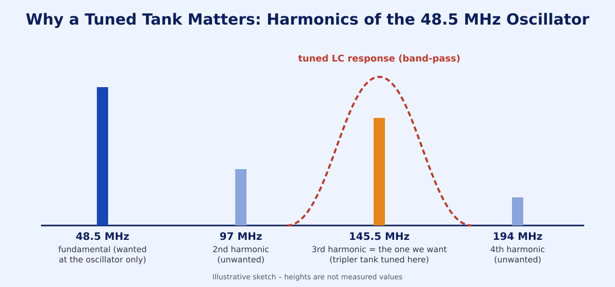
Check the tank: L2 = 7 turns, Ø6 mm, ≈ 0.15 µH. At 145.5 MHz its reactance is XL = 2πfL ≈ 137 Ω, and it resonates with about 8 pF. That is a trimmer set near its middle plus the transistor and coupling capacitance. Everything lines up.
A key FM lesson: deviation is multiplied too
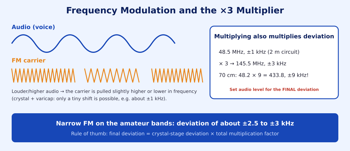
Multiplying a frequency by 3 multiplies the deviation by 3. If the crystal is pulled by ±1 kHz, the 145.5 MHz signal deviates ±3 kHz, about right for narrow FM. On the 70 cm version the factor is 9, so the same ±1 kHz would become ±9 kHz, far too wide. The audio level must therefore be set for the final deviation. See frequency modulation.
Stage 3: Filter and Antenna
A multiplier produces unwanted products as well as the wanted one. The band-pass filter (L3, its trimmer and the two 2 pF coupling capacitors) is another resonant circuit that lets 145.5 MHz through and weakens everything else. It is the part that makes the transmitter a good neighbour on the band.
A quarter-wave whip is the simplest antenna. Its length is:
L ≈ 300 ÷ f(MHz) ÷ 4 × 0.95
For 145.5 MHz that gives about 49 cm. For 433.8 MHz it gives about 16.4 cm. The 0.95 factor is a typical shortening for real wire, and a ground plane or the case acts as the other half of the antenna.
The Same Idea, Nine Times Over: The 70 cm Version
The 70 cm design simply adds a second tripler: 48.2 MHz → 144.6 MHz → 433.8 MHz. The coils get smaller (3 turns, ≈ 27 nH) because the frequency is higher; at 433.8 MHz about 5 pF resonates with 27 nH. Layout becomes critical at UHF: lead lengths of a few millimetres matter.
The Two Circuits
2 m (145.5 MHz)
70 cm (433.8 MHz) with the corrected label
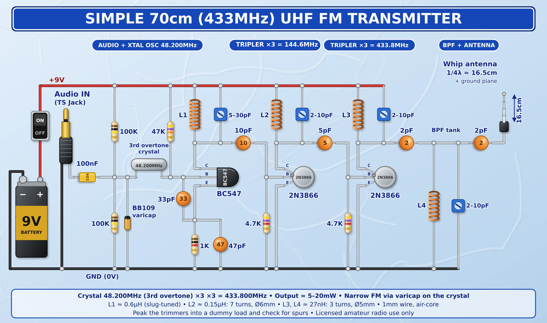
What Each Part Does
| Part | Role |
|---|---|
| 48.5 MHz overtone crystal | Sets a stable frequency |
| BC547 + 47 kΩ / 1 kΩ / 33 pF / 47 pF | Oscillator bias and feedback |
| L1 + 5–30 pF trimmer | Selects the overtone rather than the fundamental |
| BB109 varicap, 2 × 100 kΩ, 100 nF | FM modulator: bias and audio coupling |
| 2N3866, 4.7 kΩ | Class-C tripler |
| L2 + 2–10 pF trimmer | Tank tuned to the 3rd harmonic |
| L3 + trimmer, 2 pF × 2 | Band-pass filter |
| ¼ λ whip | Radiates the signal |
Before You Build: Practical Lessons
- Add supply decoupling. Put a 100 nF ceramic and a 10 nF capacitor close to the supply point of each stage, with short leads.
- Control the audio level. Add a small potentiometer (and ideally a limiter) in front of the varicap. Too much audio means too much deviation, which sounds distorted and splatters onto neighbouring channels.
- Build tight. Use a copper-clad board “dead bug” or “Manhattan” style with short leads. Breadboards do not work at VHF/UHF.
- Screen the stages and keep the coils apart (or at right angles) to avoid stray coupling.
- Use a 9 V battery for clean power. Switch-mode supplies add noise.
How to Tune It, One Stage at a Time
- Dummy load first. Never tune into an antenna. Use a dummy load or a small attenuator.
- Oscillator. Power only the BC547 stage. Use a frequency counter, an SDR, or a receiver with a short probe loop to find 48.5 MHz. Adjust L1 and the 5–30 pF trimmer until it starts reliably and stays on 48.5 MHz, not 16.17 MHz.
- Tripler. Switch on the 2N3866 stage. Peak the L2 trimmer for maximum signal at 145.5 MHz, using a relative-level meter (an RF detector or SDR).
- Band-pass filter. Peak the last trimmer, then re-touch the others. They interact.
- Check for spurs. Look at 97 MHz, 194 MHz and the oscillator frequency. They should be far below the wanted signal. If you see strong ones, re-peak the filter. A spectrum analyser or an SDR is the best way to see this.
- Modulation. Feed in audio and listen on a nearby receiver. Reduce the audio level until the voice is clean at the correct deviation.
Think Like an Engineer: Try These Questions
- If the crystal was 48.000 MHz, which frequency and antenna length would the 2 m circuit need?
- Why does a high-Q tank reject the 2nd harmonic better than a low-Q one?
- What happens to deviation if you added a third tripler?
- Why is a ¼-wave whip without a ground plane a poor antenna?
- Using f = 1/(2π√LC), what capacitor does a 0.15 µH coil need to resonate at 144.6 MHz?
Licensing: Read This Before Transmitting
Building and testing into a dummy load is legal learning. Radiating a signal is not. In Malaysia, transmitting on amateur frequencies requires an amateur radio licence with callsign issued under the Malaysian Communications and Multimedia Commission (MCMC) rules. Keep to your licence class, the permitted bands, power and modes, and identify with your callsign. Home-built transmitters must be checked for spurious output before they go on the air. When in doubt, ask an experienced operator, an Elmer, at your club.
Closing Thoughts
This little project shows why amateur radio is such a good teacher: one design combines oscillators, resonance, modulation, harmonics, filtering and antennas, and you can see, hear and measure each of them. The next time you look at a schematic, ask the Elmer’s question: “What is this stage’s job?” Then trace the signal from left to right, and the picture will start to make sense.
Want to go further? The ARRL Handbook and the RSGB Radio Communication Handbook both have excellent chapters on oscillators, multipliers and filters. Bring your questions, and your soldering iron, to the next JASRA activity.


