



Why does a handheld radio that struggles inside the town suddenly reach a friend over 100 km away when you stand on a hilltop? The answer is one short formula, and every radio amateur should know it by heart.
A story from the hill
(An illustrative story. The character is fictional; the numbers are calculated with the formula below.)
Amir lives in a busy town in southern Johor. Every Saturday evening he calls his friend Kamal on the 2 m band using a 5-watt handheld. From the ground, with the radio at about 1.5 m above the street and surrounded by shop-houses, he can only just reach Kamal’s home station about 15 to 20 km away. Kamal’s antenna is on a 10 m mast.
One weekend the JASRA members organise a hilltop activity at about 650 m above sea level. Amir climbs up, extends his antenna, and calls Kamal again. This time Kamal answers with a full, clear signal. “Where are you?” asks Kamal. “On top of the hill,” says Amir. “Same radio, same power, same antenna.” Kamal is 110 km away.
Amir did not gain a single extra watt. What changed was his height, and with it his radio horizon.
What is the radio horizon?
VHF and UHF signals (30 MHz to 3 GHz, which includes the popular 2 m 144–146 MHz and 70 cm 430–440 MHz amateur bands) travel mostly in a straight line. The Earth, however, is curved. Beyond a certain distance the ground itself rises between two antennas and blocks the direct path. That limit is the radio horizon, and links that rely on the direct path are called line-of-sight (LOS) links.
The radio horizon is slightly farther than the optical horizon. The atmosphere is normally denser near the ground than higher up, so radio waves bend gently downward, following the Earth’s curve a little. Engineers handle this by pretending the Earth is bigger than it is: the effective Earth radius factor k = 4/3, the value used for a standard atmosphere in ITU-R P.453, which gives an effective radius of about 8,500 km instead of the real 6,371 km.
The formula, step by step
For one antenna at height h above a smooth Earth of radius R, the distance to its horizon is approximately √(2·k·R·h). With R = 6,371 km, k = 4/3 and h in metres, this becomes:
dhorizon ≈ 4.12 · √h km
(Without refraction, k = 1, the constant is 3.57, which is the optical horizon.) A link has two ends, so we add the two horizons:
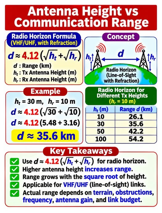
d ≈ 4.12 ( √ht + √hr )
- d – maximum radio-horizon range in kilometres
- ht – transmitting antenna height in metres
- hr – receiving antenna height in metres
If you prefer feet and miles: d (miles) ≈ 1.41 · (√ht + √hr) with heights in feet.
Tx antenna ht = 30 m, Rx antenna hr = 10 m.
d ≈ 4.12 × (√30 + √10) = 4.12 × (5.48 + 3.16) = 4.12 × 8.64 ≈ 35.6 km.
Range for different antenna heights
The table below uses the same formula. The first column of results uses a 10 m receiving antenna (a typical base station or repeater listener), the second a 1.5 m receiver (a handheld held at head height). The 10, 30, 50 and 100 m rows with hr = 10 m match the quick-reference infographic above: 26.1, 35.6, 42.2 and 54.2 km.
| Tx height ht (m) | Range d (km), hr = 10 m | Range d (km), hr = 1.5 m |
|---|---|---|
| 2 | 18.9 | 10.9 |
| 10 | 26.1 | 18.1 |
| 30 | 35.6 | 27.6 |
| 50 | 42.2 | 34.2 |
| 100 | 54.2 | 46.2 |
| 300 | 84.4 | 76.4 |
| 650 | 118.1 | 110.1 |
The square-root rule: why height has diminishing returns
Because range grows with the square root of height, you must quadruple the height of one antenna to double that antenna’s own horizon. Look at the numbers: going from 10 m to 30 m adds about 9.5 km, but going from 30 m to 100 m (an extra 70 m of tower) adds 18.6 km. Going from 2 m to 10 m adds 7 km at almost no cost, while the same gain later needs a tower. The cheapest range you will ever buy is the first few metres.
Also notice that the lower end of the link matters. A mountain-top repeater at 650 m serving a handheld at 1.5 m reaches about 110 km, but if the handheld is deep in a valley, terrain blocks it long before the formula says so.
The formula is a ceiling, not a promise
The formula tells you the maximum geometric distance over a smooth Earth. Real-world range depends on much more:
1. Terrain and obstructions
Hills, buildings, and even dense jungle canopy cut the path. The formula assumes nothing between the horizons. Always check the terrain profile with a free path-profile tool before building anything.
2. The Fresnel zone
Radio waves do not travel on a thin line but in an ellipsoid called the Fresnel zone. Engineers aim to keep at least 60 % of the first Fresnel zone free of obstacles. Its radius at the midpoint is approximately r ≈ 8.66 · √(d / f) metres, with d in km and f in GHz. For a 35 km link on 145 MHz that is about 135 m, so 60 % is roughly 80 m of clearance. On 435 MHz it is about 78 m (60 % ≈ 47 m).
3. Frequency
Lower frequencies (such as 2 m) diffract around obstacles a little better than higher ones (70 cm, 23 cm, microwaves), which behave more like light. Higher frequencies also have smaller Fresnel zones.
4. Antenna gain and the link budget
Free-space path loss is FSPL (dB) = 32.45 + 20·log10(fMHz) + 20·log10(dkm) (ITU-R P.525). For Amir’s 145 MHz link over 118 km that is about 117 dB. With 5 W (37 dBm) and a modest 7 dBi antenna at each end, the signal arrives near −66 dBm, far above a typical FM receiver’s sensitivity of about −120 dBm, so a clear line of sight makes the link easy. In a real path the margin is eaten by terrain, feed-line loss, rain, and fading, so your link budget decides whether the theoretical range is reachable.
5. Feed-line loss: a tall mast can hurt
Every extra metre of mast also needs an extra metre of coax. At VHF/UHF, thin coax such as RG-58 can lose several dB per 30 m, especially on 70 cm. Use low-loss cable (for example LMR-400 class or better) and keep it short. It is common that 3 dB lost in cable (half your power) cancels the benefit of 3 dBi of antenna gain.
6. Beyond the horizon
Signals do not stop dead at the horizon. Diffraction, scatter, and especially tropospheric ducting, which is common in warm, humid, calm weather such as ours, can carry VHF/UHF signals hundreds of kilometres. Treat these as bonuses, not as a reliable design basis. Also remember this article is about VHF/UHF line-of-sight. HF (3–30 MHz) uses ionospheric skywave and follows different rules.
Practical tips for radio amateurs
- Go high first. A hilltop, a high-rise rooftop or a few extra metres of mast is the best upgrade you can make.
- Raise the antenna, not the power. Going from 5 W to 50 W gives 10 dB; the formula shows height can do more for horizon distance.
- Use a good vertical or a directional antenna. Gain on a Yagi helps weak-signal links.
- Use low-loss coax and good connectors.
- Plan with a path-profile tool and keep 60 % of the first Fresnel zone clear.
- Handheld tip: hold the radio high and clear of your body, or use an external antenna on a vehicle roof.
- Safety first. Never work on towers alone, stay far from power lines, and use proper climbing gear. Check MCMC licensing conditions and the requirements of your local authority before erecting any structure.
Key takeaways
- ✅ Use d ≈ 4.12 (√ht + √hr) for the radio horizon in km, heights in metres.
- ✅ Higher antennas increase range.
- ✅ Range grows with the square root of height.
- ✅ It applies to VHF/UHF line-of-sight links.
- ✅ Real range depends on terrain, obstructions, frequency, antenna gain and link budget.
Have you reached a new distance record from your local hill? Share your story with the JASRA community, and 73!
Baca dalam Bahasa Melayu: Ketinggian Antena dan Jarak Komunikasi: Rahsia Ufuk Radio
References and further reading
- ITU-R Recommendation P.453 — The radio refractive index: its formula and refractivity data (effective Earth radius factor k). https://www.itu.int/rec/R-REC-P.453
- ITU-R Recommendation P.526 — Propagation by diffraction. https://www.itu.int/rec/R-REC-P.526
- ITU-R Recommendation P.525 — Calculation of free-space attenuation. https://www.itu.int/rec/R-REC-P.525
- Wikipedia — Radio horizon. https://en.wikipedia.org/wiki/Radio_horizon
- Wikipedia — Line-of-sight propagation. https://en.wikipedia.org/wiki/Line-of-sight_propagation
- Wikipedia — Fresnel zone. https://en.wikipedia.org/wiki/Fresnel_zone
- ARRL — The ARRL Antenna Book and The ARRL Handbook (VHF/UHF propagation, antenna height and feed-line loss chapters). https://www.arrl.org/shop
- Malaysian Communications and Multimedia Commission (MCMC) — amateur radio licensing information. https://www.mcmc.gov.my
- Persatuan Jalur Selatan Radio Amatur Malaysia (JASRA). https://www.jasra.org.my
Figures are computed by the formula shown; they are theoretical maxima and not guarantees. Illustrations are original JASRA drawings, and the infographic is a summary of the same formula.


