



A short story and a practical guide for new and old hams. Fictional characters, real physics.
Antenna Parameters
Gain · Directivity · Impedance · VSWR · Bandwidth · Efficiency
JASRA
The story of Rina’s first dipole
Rina had just passed her amateur radio exam in Johor. Her first goal was simple: join the Sunday morning net on 40 metres. She had a transceiver, a roll of coax and a spool of wire. What she did not have was a feel for the antenna.
She cut a wire, hung it between two trees and connected the coax. The SWR meter swung to 3:1. “Is it broken?” she asked her Elmer, Pak Din. He laughed. “No. It is just telling you something. Let me introduce six words, and you will understand every antenna you ever meet: gain, directivity, impedance, VSWR, bandwidth and efficiency.”
The simple chart below, which many of us have seen shared around, is a good summary of those six words. Let us walk through them with Rina.
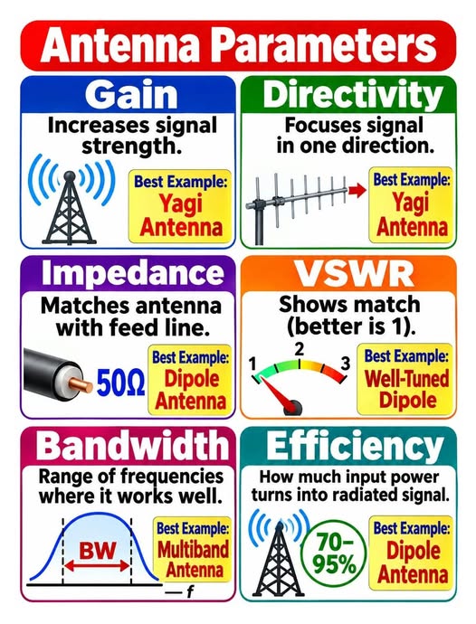
1. Impedance: can the radio and the antenna “shake hands”?
Most transceivers expect a load of 50 Ω, and most coax cable is 50 Ω. A half-wave dipole in free space has a feed-point impedance of about 73 Ω. Close enough to work very well, which is why the dipole is the classic “best example” for impedance. When the antenna impedance differs from the line, part of the power bounces back. Matching tools (a balun, a matching section or an antenna tuner) exist to fix that.
Rule of thumb: impedance is about matching, not about how strong the signal is.
2. VSWR: the match meter
VSWR (voltage standing wave ratio, usually just SWR) tells you how good that match is. 1:1 is perfect; higher numbers mean more power reflected. Rina’s 3:1 told her the antenna was far from resonance on her chosen frequency. The wire was too long (the dipole length is roughly 142.5 / fMHz metres, so about 20 m for 7.1 MHz, and real-life trees and height change it).
| SWR | Reflected power | Return loss | Verdict |
|---|---|---|---|
| 1.0 : 1 | 0 % | infinite | Perfect |
| 1.5 : 1 | 4 % | 14 dB | Very good |
| 2.0 : 1 | 11 % | 9.5 dB | Acceptable |
| 3.0 : 1 | 25 % | 6 dB | Needs work |
| 5.0 : 1 | 44 % | 3.5 dB | Poor |
She shortened the wire a little at a time, and the SWR fell to 1.3:1. That is the picture of a “well-tuned dipole” in the chart.
3. Bandwidth: how wide is the sweet spot?
An antenna is tuned to a frequency, but it works over a range. Bandwidth is usually the span where SWR stays below a chosen limit, often 2:1. A thin-wire dipole on 40 m covers a modest slice of the band; a fat-element or multiband antenna covers more, which is why a multiband antenna is the example for bandwidth. Sweep your SWR across the band and you will see the curve below.
4. Efficiency: how much of your power really leaves?
Efficiency is radiated power divided by input power. Heat in the wire, poor ground, lossy coax, traps and loading coils all eat power. A good dipole in the clear can reach 70 to 95 % as in the chart, while a short loaded mobile whip may be far lower. A very important warning: low SWR does not mean high efficiency. A dummy load has a perfect 1:1 SWR and radiates nothing at all!
5. Directivity: pointing the signal
An antenna does not create power; it only chooses where the power goes. Directivity measures how concentrated the radiation is in its best direction compared with the average of all directions. A Yagi squeezes the energy into a beam, like the reflector of a torch. A dipole is gentler, with a figure-8 pattern.
6. Gain: directivity with the losses subtracted
Gain = directivity × efficiency. We quote it in dBi (against an imaginary isotropic radiator) or dBd (against a dipole; dBi = dBd + 2.15). Every 3 dB doubles the effective power in the favoured direction, and no extra watt is created. That is why Pak Din’s 5-element Yagi, with roughly 10 dBi, makes his 5-watt handheld sound like a much stronger station on the repeater: he points the energy at the target instead of at the sky and the neighbours.
Isotropic (reference)Same in every direction: 0 dBi
Half-wave dipoleFigure-8: 2.15 dBi, broadside to the wire
Yagi (illustrative)One main lobe: roughly 7-10 dBi
▲ front
Schematic patterns for teaching; not measured data. Outer ring = strongest direction of each antenna.
Quick summary
| Parameter | In one line | Classic example |
|---|---|---|
| Gain | Signal strength increase in the best direction (dBi / dBd) | Yagi |
| Directivity | How focused the beam is | Yagi |
| Impedance | Matching antenna to feed line (50 Ω) | Dipole |
| VSWR | How good the match is (1:1 is best) | Well-tuned dipole |
| Bandwidth | Range of frequencies where it works well | Multiband antenna |
| Efficiency | Input power that becomes radiated signal | Dipole |
The ending
On Sunday morning Rina called CQ on 7.1 MHz. A station in Melaka answered, then one in Singapore. “Five and nine,” said the first. Her wire in the trees was not a fancy antenna, but she now understood why it worked, and what to try next. That is the best gift an antenna chart can give.
Try it yourself: measure the SWR at the bottom, middle and top of your favourite band, write the numbers down, and draw your own bandwidth curve. Then share it on our JASRA channels. 73!
References
- Balanis, C. A. Antenna Theory: Analysis and Design, 4th ed., Wiley, 2016 (gain, directivity, efficiency, bandwidth).
- ARRL. The ARRL Antenna Book. arrl.org/arrl-antenna-book
- IEEE Std 145-2013, IEEE Standard for Definitions of Terms for Antennas.
- Wikipedia, Antenna gain
- Wikipedia, Directivity
- Wikipedia, Standing wave ratio
- Wikipedia, Impedance matching
- Wikipedia, Dipole antenna
- Wikipedia, Yagi–Uda antenna
- Wikipedia, Antenna (radio)
- Summary chart: Arashad Mohamed, Facebook post (link).
Characters are fictional. Pattern, SWR-curve and power-budget drawings are teaching illustrations, not measurements.


