



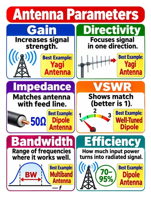
Six words on one colourful chart: gain, directivity, impedance, VSWR, bandwidth and efficiency. Every radio amateur uses them, but not everyone can explain them. This is the story of how one JASRA member finally understood all six.
A story from the club station
(An illustrative story. The characters are fictional; all numbers are calculated from the standard formulas below.)
Amir has just passed his amateur radio exam. For his first weekend he puts a simple wire dipole on the roof and calls his friend Kamal on the 2 m band. It works, but Kamal’s signal is stronger. “What antenna are you using?” asks Amir. “A 5-element Yagi, and my SWR meter reads 1.2,” says Kamal. “Come to the club station on Saturday and I will show you what that means.”
On Saturday, the club’s senior member Pak Long draws six boxes on the whiteboard. “Every antenna is described by the same six parameters,” he says. “Learn them and you can choose, build and fix any antenna.” Amir takes out his phone and photographs the chart above. Here is what he learned.
1. Gain: how much stronger, compared with what?
Gain tells you how much stronger the signal is in the best direction, compared with a reference antenna, for the same input power.
Gain is measured in decibels. The reference matters: dBi compares with an imaginary isotropic radiator that sends power equally in every direction, while dBd compares with a half-wave dipole. A half-wave dipole has about 2.15 dBi of gain, so dBi = dBd + 2.15.
A typical 3-element Yagi gives about 7 dBi, a 5-element about 10 dBi and a long 10-element about 13 dBi (typical values; real antennas vary). Every +3 dB doubles the effective radiated power, and +10 dB multiplies it by ten. Antenna gain is not free power: the antenna only takes energy from the sides and puts it into the beam, which is why a high-gain antenna must be aimed.
Best example from the infographic: the Yagi. “That is why my signal was stronger,” Amir realises. “Kamal’s beam added about 8 dB over my dipole.”
2. Directivity: where does the signal go?
Directivity describes how tightly the antenna focuses its radiation into one direction. It is the shape of the pattern.
A dipole sends signal broadside, in a wide figure-8 shape. A Yagi adds a reflector behind and several directors in front of the driven element, which squeezes the pattern into one narrow beam. A narrow beam has a small beamwidth (measured between the half-power, or −3 dB, points), and a high front-to-back ratio, which also rejects interference from behind.
The trade-off: the more directive the antenna, the more carefully you must point it. A rotator is the radio amateur’s answer.
Gain versus directivity: the connection
Pak Long writes one line on the board: Gain = Efficiency × Directivity. Directivity assumes a perfect, loss-free antenna. Gain also counts what is lost as heat. For a good antenna the two are almost the same number; for a poor one, gain is lower.
Efficiency (η)how much is radiated
Directivity (D)where it is pointed
lost as heat (feed line, ground, wire)
Gain = Efficiency × Directivity
G (dBi) = D (dBi) + 10 log₁₀ η
Example: D = 10 dBi and η = 80 % → 10 − 0.97 ≈ 9.0 dBi
3. Impedance: matching the antenna to the feed line
Impedance is the “electrical size” the antenna presents to the transmitter. The feed line and the antenna should agree, normally on 50 Ω.
Most amateur transmitters and coaxial cables are designed for 50 Ω. Power moves best when the antenna, feed line and transmitter all show the same impedance. A half-wave dipole in free space has a feed-point impedance of about 73 Ω, and at a typical height above real ground it commonly falls toward 50–70 Ω. That is close enough to 50 Ω for coax (a balun is recommended to stop current flowing on the outside of the coax). A folded dipole is about 300 Ω and a quarter-wave vertical about 36 Ω, which is why they use a transformer or matching section.
The antenna impedance is a complex number: resistance R plus reactance jX. At resonance the reactance is zero and only the resistance remains. A matching device, such as an antenna tuner, a gamma match, a balun or a quarter-wave transformer, is used when the numbers do not agree.
Best example from the infographic: the dipole on a 50 Ω line.
4. VSWR: the match meter
VSWR (Voltage Standing Wave Ratio) shows how well the match is. 1 is perfect; the higher the number, the more power bounces back.
When the impedances do not match, part of the power is reflected back toward the transmitter. The reflected wave and the forward wave combine into a standing wave, and the ratio between its maximum and minimum voltage is the VSWR. For a load of impedance ZL on a line of impedance Z0:
Γ = (ZL − Z0) / (ZL + Z0) VSWR = (1 + |Γ|) / (1 − |Γ|)
| VSWR | Reflection coeff. Γ | Return loss (dB) | Power reflected | Mismatch loss (dB) | Verdict |
|---|---|---|---|---|---|
| 1 : 1 | 0.00 | ∞ | 0 % | -0.00 | Perfect |
| 1.5 : 1 | 0.20 | 14.0 | 4 % | 0.18 | Excellent |
| 2 : 1 | 0.33 | 9.5 | 11 % | 0.51 | Acceptable |
| 3 : 1 | 0.50 | 6.0 | 25 % | 1.25 | Poor, check it |
| 5 : 1 | 0.67 | 3.5 | 44 % | 2.55 | Fix it first |
Look at the numbers. At 2:1, about 11 % of the power is reflected, but the loss is only about 0.5 dB, far less than one S-unit (6 dB), and you would hardly hear it. That is why many amateurs treat 2:1 as acceptable and 1.5:1 as excellent. The real risk is not the loss at the antenna; it is that some solid-state transmitters automatically reduce power when the VSWR is high, and that loss in the coax is amplified on a mismatch, especially at VHF and UHF with long runs of thin cable.
A very low reading is also not proof that the antenna is good: a dummy load shows 1:1 but radiates nothing. “A low VSWR means a good match, not a good antenna,” says Pak Long. Best example from the infographic: a well-tuned dipole.
5. Bandwidth: how wide is the usable range?
Bandwidth is the range of frequencies where the antenna still works well, usually where SWR stays under a chosen limit such as 2:1.
Every resonant antenna works best at its centre frequency and gets worse on either side. Bandwidth is measured between the two frequencies where the SWR rises to the chosen limit, and often quoted as a percentage of the centre frequency. A thick element, a folded dipole or a cage or “fan” dipole has a wider bandwidth; a thin wire or a very short antenna has a narrower one. A high-gain Yagi usually has a narrower bandwidth than a simple dipole, which is why long beams are built for one part of a band.
On the 2 m band (144–146 MHz) bandwidth is rarely a problem. On the 80 m band (3.5–3.9 MHz, a bandwidth of more than 10 % of the frequency) a simple dipole can cover only a part of the band without a tuner. A multiband antenna, shown in the infographic, such as a trap dipole, a fan dipole or a multiband vertical, is designed to be usable on several bands.
6. Efficiency: how much power is really radiated?
Efficiency is the share of the power you put in that is actually radiated as a signal, rather than lost as heat.
Efficiency is the radiation resistance divided by the total resistance: η = Rr / (Rr + Rloss). The infographic gives 70–95 % for a dipole. A full-size, well-built dipole is very efficient, and the lower end of that range may be reached with poor ground, near buildings or with lossy connectors.
Efficiency falls sharply for antennas that are much smaller than a wavelength, such as a short “rubber duck” on a handheld, a loaded mobile whip, or a small loop on 40 m. Their radiation resistance is very small, so the loss resistance of the coil and the ground becomes large in comparison. A compact antenna can show a perfect 1:1 SWR and still radiate only a small percentage of the power. As Pak Long says, “SWR tells you about the match, not the efficiency.”
All six at a glance
| Parameter | Question it answers | Typical unit | Good example |
|---|---|---|---|
| Gain | How much stronger in the best direction? | dBi / dBd | Yagi |
| Directivity | How focused is the beam? | dBi, beamwidth (°) | Yagi |
| Impedance | Does it agree with the feed line? | Ω (R + jX) | Dipole on 50 Ω coax |
| VSWR | How much power is reflected? | ratio, 1:1 to ∞ | Well-tuned dipole |
| Bandwidth | Over what frequency range is it usable? | kHz, MHz, % of centre | Multiband antenna |
| Efficiency | How much input power is radiated? | % | Full-size dipole (70–95 %) |
What Amir did next
That evening Amir raised his dipole higher (see our article on antenna height and the radio horizon), trimmed the ends until his SWR meter showed 1.3:1 at the middle of the 2 m band, and replaced his thin coax with a low-loss cable. Next month he is building a 3-element Yagi from aluminium tube. “Six parameters,” he says, “and now I know which one to blame.”
Practical tips for radio amateurs
- Check the match first. Measure SWR with a meter or an antenna analyser, at the bottom, middle and top of the band, then trim to centre it.
- Do not chase 1.0:1. Below about 1.5:1 the gain in power is negligible. Better to spend time raising the antenna.
- Use good coax and connectors. Cable loss grows with frequency and length, and a mismatch makes it worse.
- Use a balun or choke with dipoles to keep RF off the coax and out of the shack.
- Pick gain for the job. Gain helps when you know where the other station is. A simple vertical or dipole is better for general calling and nets.
- Remember small means lossy. A compact antenna is a compromise; expect less than a full-size one.
- Safety first. Never erect antennas near power lines, work on towers alone, and observe RF exposure limits. Follow the MCMC licence conditions in Malaysia.
Key takeaways
- ✅ Gain = directivity × efficiency; measured in dBi or dBd.
- ✅ Directivity is the focus of the beam; a Yagi has more than a dipole.
- ✅ Impedance should match the feed line, normally 50 Ω.
- ✅ VSWR of 1 is perfect; 2:1 is usually acceptable.
- ✅ Bandwidth is the frequency range with SWR below the limit.
- ✅ Efficiency says how much power is really radiated; a good dipole reaches 70–95 %.
Which parameter surprised you the most? Tell us at the next JASRA meeting, and 73!
References and further reading
- Balanis, C. A. Antenna Theory: Analysis and Design, 4th ed., Wiley, 2016. Definitions of gain, directivity, efficiency, input impedance and bandwidth.
- Kraus, J. D. and Marhefka, R. J. Antennas for All Applications, 3rd ed., McGraw-Hill, 2002.
- ARRL. The ARRL Antenna Book (current edition). Practical antenna building, feed lines and SWR for radio amateurs. https://www.arrl.org/arrl-antenna-book
- IEEE Std 145-2013, IEEE Standard for Definitions of Terms for Antennas. The formal definitions of gain, directivity and efficiency.
- Pozar, D. M. Microwave Engineering, 4th ed., Wiley, 2012. Reflection coefficient, return loss and VSWR.
- Wikipedia: Antenna (radio) https://en.wikipedia.org/wiki/Antenna_(radio)
- Wikipedia: Antenna gain https://en.wikipedia.org/wiki/Antenna_gain
- Wikipedia: Directivity https://en.wikipedia.org/wiki/Directivity
- Wikipedia: Antenna efficiency https://en.wikipedia.org/wiki/Antenna_efficiency
- Wikipedia: Impedance matching https://en.wikipedia.org/wiki/Impedance_matching
- Wikipedia: Standing wave ratio https://en.wikipedia.org/wiki/Standing_wave_ratio
- Wikipedia: Dipole antenna https://en.wikipedia.org/wiki/Dipole_antenna
- Wikipedia: Yagi–Uda antenna https://en.wikipedia.org/wiki/Yagi%E2%80%93Uda_antenna
- Infographic “Antenna Parameters”, shared in a Facebook post by Arashad Mohamed (original creator not stated). https://web.facebook.com/arashad.mohamed.50/posts/pfbid0omtUyU7PNoJfJkf2U8fspLYRtb7MhsbxqEbURdGArtaB3ZUp7G5zNh77BC4jJJzBl
Numbers in the tables and charts are calculated from the standard formulas; gain values for Yagi antennas are typical figures and vary with design. Illustrations (pattern, VSWR, bandwidth and gain diagrams) are original JASRA drawings and are schematic. The infographic is shared for educational purposes; the original creator is not stated in the source post.


